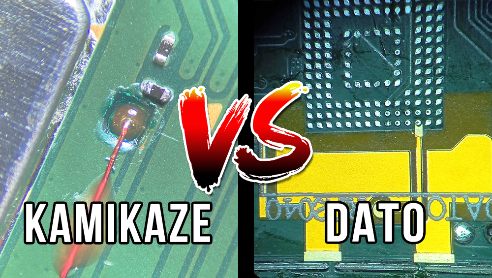
Nintendo Switch OLED Modding: DAT0 vs. Kamikaze Method
Modding the Nintendo Switch OLED requires precision-level board work due to changes Nintendo made to the motherboard layout compared to earlier Switch revisions. Unlike launch-era consoles, the OLED model does not expose certain required signals in easily accessible locations. As a result, installers rely on two primary techniques to access the critical DAT0 signal from the eMMC storage:
- The DAT0 adapter (pogo-style) method
- The Kamikaze (direct drill and solder) method
Both approaches achieve the same electrical goal, but they differ significantly in execution, risk profile, and long-term reliability.
Understanding the DAT0 Signal
The DAT0 line is part of the eMMC NAND interface and is required for proper modchip communication. On the OLED motherboard, this signal is not readily available on a convenient surface test pad. Installers must either access it via contact at the NAND pad itself or expose it by penetrating the board.
This is where the two methods diverge.
The DAT0 Adapter Method (Pogo Contact)
The DAT0 method uses a precision adapter that incorporates a pogo-style spring contact pin. Rather than modifying the motherboard permanently, the adapter is positioned so the pogo contact makes direct pressure-based contact with the correct DAT0 pad on the NAND chip.
How it Works
- The NAND chip remains intact and undrilled.
- A specially designed adapter aligns under the NAND region.
- A spring-loaded contact touches the DAT0 pad directly.
- The modchip routes the signal through this adapter.
This is a contact-based approach rather than a destructive one. No internal PCB layers are drilled, and no internal traces are exposed.
Characteristics
- No drilling into the motherboard
- No permanent structural alteration
- Signal obtained via controlled contact
- Maintains full board integrity
Because the connection relies on alignment and mechanical stability, installation quality is critical. When properly executed, this method preserves the motherboard while achieving stable electrical performance.

The Kamikaze Method (Drill and Direct Solder)
How it Works
- A micro-drill penetrates the PCB layers at a precise location.
- The internal DAT0 copper trace is exposed.
- A wire is soldered to that internal trace.
Characteristics
- Permanent alteration of the motherboard
- No permanent structural alteration
- Internal PCB layers are physically penetrated
- Direct copper solder joint

Risk and Reliability Comparison
Both methods can function when executed correctly, but they differ in risk tolerance and philosophy.
DAT0 Adapter Method
- Preserves board structure
- Lower catastrophic failure risk
- More serviceable long-term, if it ever fails it can easily be repaired.
- Relies on mechanical precision
Kamikaze Method
- Permanent structural modification
- Higher risk if drilling depth or location is incorrect
- Electrically direct but physically invasive
From a risk-management standpoint, avoiding irreversible structural damage reduces worst-case scenarios and improves long-term serviceability.
Our Approach at Wayayeo
We still strongly recommend and primarily use the DAT0 adapter for OLED modding, properly installed, it delivers consistent, trouble-free performance with zero future issues expected.
For those wanting the ultimate in reliability, we’re now offering the Kamikaze method as a premium upgrade. It provides a direct, soldered DAT0 connection for unmatched long-term stability (no adapter slip or heat-related failures). Due to the increased complexity, precision required, and time involved, this option costs more.
Choose what fits your priorities — we’re here to deliver top-tier results either way.


